Creating Soft Sockets and 3D Scans from Plaster Casts
# Creating Soft Sockets and 3D Scans from Plaster Casts
---
For more pictures of soft socket creation, [check out the gallery](https://hub.e-nable.org/u/kreeser1/gallery/custom-gallery/view?openGalleryId=84#.jpeg).
For more pictures of creating and post-processing plaster casts, [check out the gallery](https://hub.e-nable.org/u/kreeser1/gallery/custom-gallery/view?openGalleryId=85#.jpeg).
For more pictures of 3D scanning, [check out the gallery](https://hub.e-nable.org/u/kreeser1/gallery/custom-gallery/view?openGalleryId=86#.jpeg).
---
During my time at [Lake Victoria Disability Centre](wiki:/u/kreeser1/wiki/Lake+Victoria+Disability+Centre "Lake Victoria Disability Centre") and [HVP-Gatagara](wiki:/u/kreeser1/wiki/HVP-Gatagara+and+ORTHOLAB%3A+An+Introduction "HVP-Gatagara and ORTHOLAB: An Introduction"), I had the opportunity to see and take part in the many steps of making traditional prosthetic devices. This article aims to detail how plaster casts of residual limbs are produced, how traditional soft sockets are made, and how through the use of 3D scanning technology, digital models of these casts and sockets are created.
### Creating a Plaster Cast
The process of creating a plaster cast begins with draping the patient with a plastic tarp to prevent plaster from getting onto their clothes, or onto unintended parts of their body. Petroleum jelly is applied lightly to the residual limb to aid in release of the cast after the plaster bandages have cured. In certain cases, the limb may need to be shaved to further aid in the release of the cast. The prepared limb is wrapped with water-soaked plaster bandages, often with a rubber tube or other piece of material (a piece of metal or plastic) against the skin to protect the limb when cutting the cured cast away from the body in a later step. During application of the water-soaked plaster bandages, the bandages are massaged against the residual limb to smooth any seams or ripples in the material and to conform the bandages to the residual limb as best as possible. The plaster is allowed to set, taking approximately 15-20 minutes. The negative casts are removed from the limb by carefully cutting down one side with a razor, following the underlying rubber tube or other piece of protective material, perpendicular to a series of horizontal lines drawn in skin-marking pencil. The horizontal lines are drawn for reference to ensure the seam of the cast can be closed and aligned properly later.

###### Upper Left: Kyle Reeser wraps a patient’s torso and lap in a plastic drape. Upper Middle: Water-soaked plaster bandages are wrapped around the patient’s residual limb, with a piece of rubber tubing to cut along when removing the cast later. Upper Right: Kyle Reeser wraps a patient’s residual limb with water-soaked plaster bandages. Lower Left: Rajab Hamis wraps a water-soaked plaster bandage around the patient’s residual limb, with a piece of rubber tubing to cut along when removing the cast later. Lower Middle: Water-soaked plaster bandages are wrapped around the patient’s residual limb, with a piece of rubber tubing to cut along when removing the cast later. Lower Right: Cutting the cured plaster cast with a razor blade along the underlying rubber hose.
---
Contours and measurements taken from the patient are sketched into the inside of the plaster cast with a skin-marking pencil, followed by skirting the cast with additional plaster bandage to make the rim of the opening even.

###### Views of a negative plaster cast of a patient’s residual limb (left limb). Note the markings in skin-marking pencil (blue).
---
Petroleum jelly is applied lightly to the inside of the negative cast, and a liquid plaster mixture is poured in. A metal rod is positioned within the cast, now serving as a mold, for ease of handling after the plaster positive cures and is removed from the mold. The plaster positive takes approximately 45-60 minutes to fully cure, and is removed by cutting away the negative mold that surrounded it.

###### Views of a negative plaster cast being filled with liquid plaster and a metal rod, and allowed to set. The negative plaster cast ‘mold’ is later removed to reveal a positive plaster cast.
---
The result is a positive cast that closely approximates the shape and dimensions of the patient’s residual limb. This positive cast requires significant post-processing before being used later in the process of creating a thermoformed soft socket.

###### A positive plaster cast after removal from the negative plaster cast ‘mold’, with a tack indicating the height to which more plaster should be added along the bone.
---

###### Plaster (tinted slightly blue with methylene blue) is added to the positive plaster cast in post-processing.
---
### Creating a Soft Socket
---
*Premia Bond contact adhesive, manufactured by: Dynamic Chemicals Ltd. (Nairobi)
Suitable for bonding leather, rubber, plastic, floor tiles, ceramic, wood, Formica, glass, metal, and textiles*
1. *Ensure all surfaces to be bonded are free from grease \[and\] dust, and are dry.*
2. *Apply glue to both surfaces and let it dry for 8-10 minutes.*
3. *Bring the two surfaces together and apply pressure to ensure a firm bond.*
4. *With time, the bond between the surfaces will become stronger.*
---

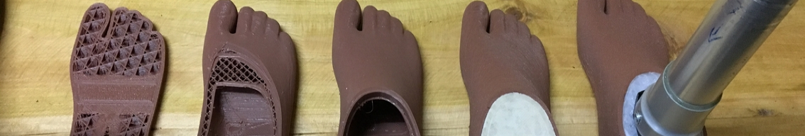
###### Upper Left: A P&O technician at HVP-Gatagara cuts out a trapezoidal shape that, when rolled into a tube, would be the approximate shape needed for a soft socket. Upper Middle: The technician uses a power sander to sand the long edges of the trapezoid at an angle. Upper Right: The technician applies contact adhesive to the long edges of the trapezoid and folds it into a tube. Lower Left: A diagram showing how the foam material is folded into a tube. Lower Right: Roberto Postelmans uses a rubber mallet to pound the seam of the foam tube to ensure strong adhesion at the seam.
---

###### Upper Left: Thermoforming of a soft socket under vacuum. Upper Right: The result or thermoforming, prior to being trimmer away. Lower Left and Lower Right: The blunt head of a vacuum system for thermoforming soft sockets. The blunt head has a large central hole through which the metal rod of the positive plaster cast can be inserted. The large and small holes of the blunt head provide vacuum.
---

###### Roberto Postelmans modifying the exterior of a soft socket with the layered buildup of foam material.
---

###### Roberto Postelmans wrapping a soft socket with PVC leather using contact adhesive.
---

###### Views of the completed soft socket, wrapped with PVC leather.
---
### 3D Scanning Plaster Casts and Soft Sockets

###### Isaac Rukundo, director of the P&O department at HVP-Gatagara, 3D scanning a plaster cast of a patient’s residual limb.
---

###### Left: A plaster cast of a patient’s residual limb. Scanning a plaster cast yields a digital model that can be used to 3D print a form-fitting soft socket. Right: A traditionally-manufactured soft socket, formed over the plaster cast from the left panel. Scanning a soft socket yields a digital model that can be used to 3D print a matching hard socket.
---
### Notes on 3D Scanning

###### Left: Roberto Postelmans using a Sense 3D scanner to scan Kyle Reeser’s hand. Right: A 3D model resulting from scanning a hand. Note the material in between the fingers of the 3D scan, a deficiency in the 3D scanner’s ability to create an accurate model to track it’s registration points on the fingers.
---
### Takeaways
### e-NABLE Community Calls to Action